|
||||||||||||||||||||||||||||||||||||||||||||||||||||||||||||||||||||
|
||||||||||||||||||||||||||||||||||||||||||||||||||||||||||||||||||||
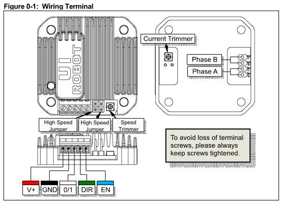
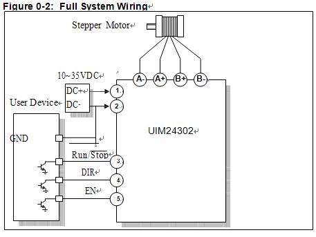
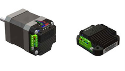
Features − Miniature size 42.3mm*42.3mm*13.5mm (L*W*H) Description UIM24302 Stepper Motor Controller is a miniature, high performance stepper motor controller. They can be mounted onto NEMA 17 / 23 series stepper motor seamlessly through corresponding flanges. The thickness of these controllers is less than 14 mm. After properly adjusting/setting the speed and direction, it can run the motor on power up without the need of user control device. It is a good replacement of a servo system in applications need low cost but not hyper accuracy. UIM24302 is capable to provide 0-2A adjustable phase current. Their mixed-decay current control reduces the back-EMF effect under high motor speed and improves the performance. Except that UIM24302 takes 10-35VDC input. Enclosure is made of die-cast aluminum which provides a rugged durable protection and improves the heat dissipation. Description of Screw Terminals
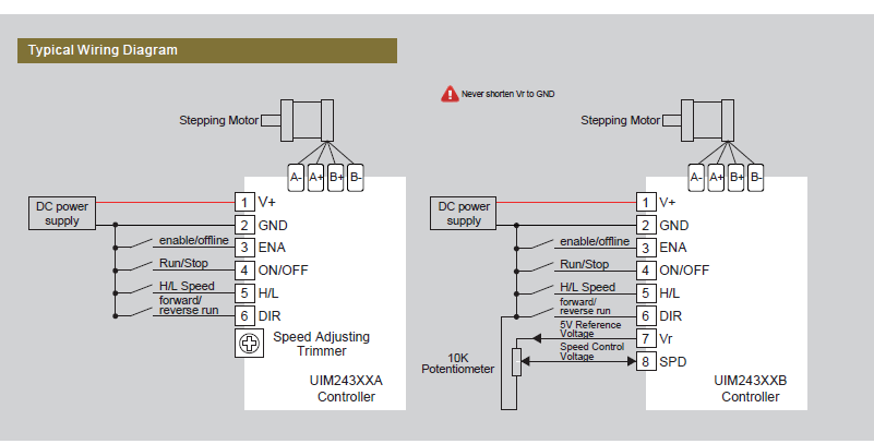
Motor Wiring Pads (bottom of the controller) Pad A + / A- : Connect to the stepper motor phase A Pad B+ / B- : Connect to the stepper motor phase B Characteristics Electrical Characteristics(Ambient Temperature 25℃)
Environment Requirements
Size and Weight
|
||||||||||||||||||||||||||||||||||||||||||||||||||||||||||||||||||||
|
||||||||||||||||||||||||||||||||||||||||||||||||||||||||||||||||||||
| ©2003 KYSAN ELECTRONICS All Rights Reserved! www.kysanelectronics.com | ||||||||||||||||||||||||||||||||||||||||||||||||||||||||||||||||||||